Once you have determined that the u-joints need replacing then replacing U-joints can be a do-it-yourself project provided you have the right tools, willingness to get a bit dirty and working on your back. This DIY project is not necessarily all that expensive with parts usually running between $25.00 and $35.00 each.
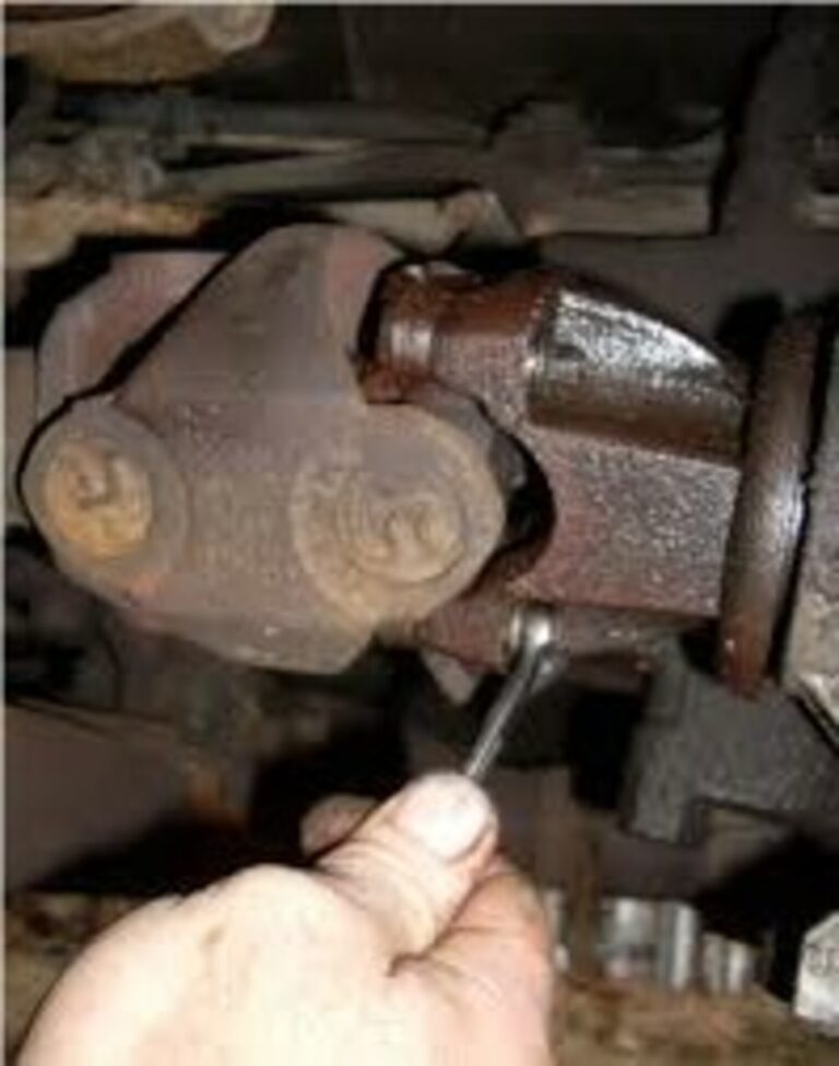
Odds are, you will need to raise the vehicle off the ground (unless you are driving a giant-wheeled 4×4). Ramps are great for this, but a floor jack and a pair of jack stands will do the job fine. Replacing U-joints, unscrew the nuts of the U-bolts that clamp the universal’s cups to the rear axles yoke. Mark the parts so that you can put them back the way they were. Using a big screwdriver, pry the shaft forward until the joint is free of the yoke, then lower it and pull it out of the transmission tail shaft housing.
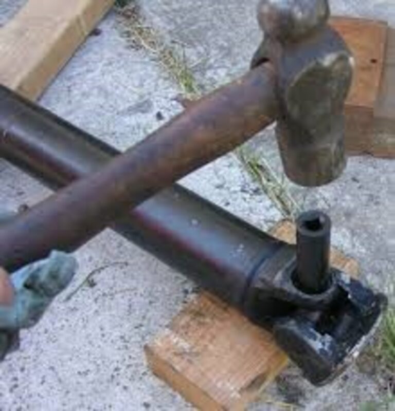
While a hydraulic press is ideal for driving the cups out of the yoke ears, you might be able to manage with a husky bench vise. Or you can drive the cups out with a drift and a heavy hammer.
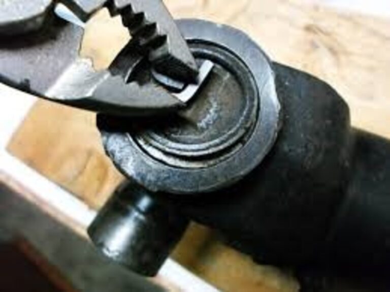
If these are the originals, they are probably retained by injected nylon, which will simply be destroyed in the process. Another option is to see if there are C-clips in grooves in the inner or outer sides of the ears. The inner type can be forced out easily with a screwdriver and hammer, but you may need snap-ring pliers for the outer variety.
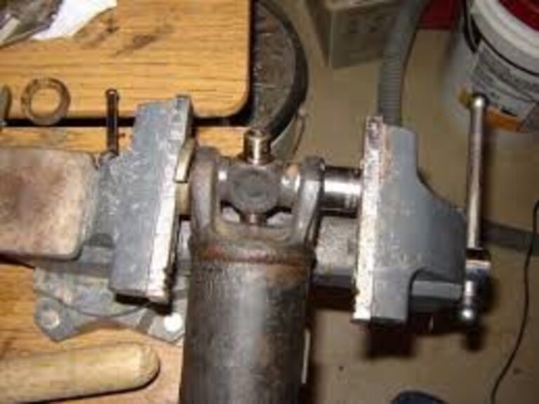
Whether you are using a vise or a drift and hammer, place a socket that is bigger than the outside diameter of the cup against one ear to accept the cup. Then, with a vise, put a smaller socket on the other cup to push it through the hole in the ear. Now, turn the vise screw as necessary to force the cups through the yoke. If you are doing the pounding routine, position the large socket under one ear and use a big drift against the opposite cup. This probably will take an extra pair of hands.
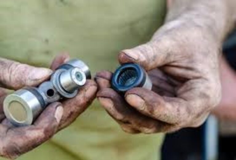
When it comes to installing the new joint, first make sure it was packed with grease at the factory. The cups should be filled to about one-half of the needle length with the proper grease (usually SAE 140). While forcing the cups into place, you must be careful not to dislodge the needle bearings or jam them at an angle.
Remove the nuts on the U-bolts at the rear axle to disassemble the driveshaft.
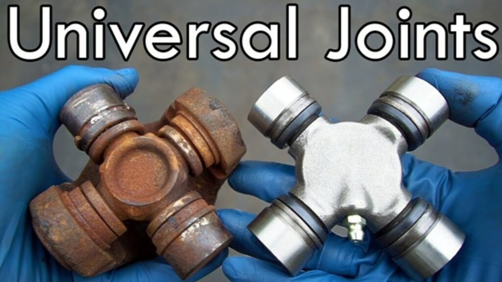
Dry U-joints will have rust inside, not grease. Do not try to save one that is rusty. Replace it.
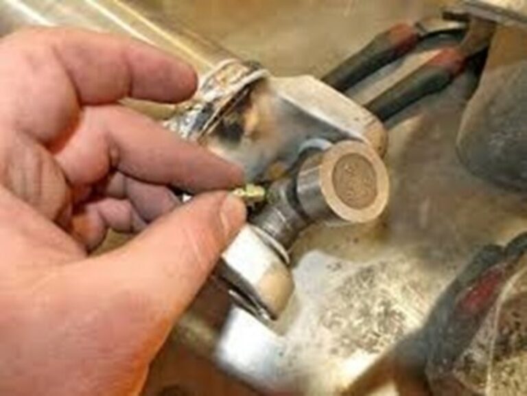
A new U-joint should have a zerk fitting even if the original did not. Fill the joint with grease until it runs out of the seals after it is installed in the yoke.
Shaft Shivers may cause early failure of u-joints
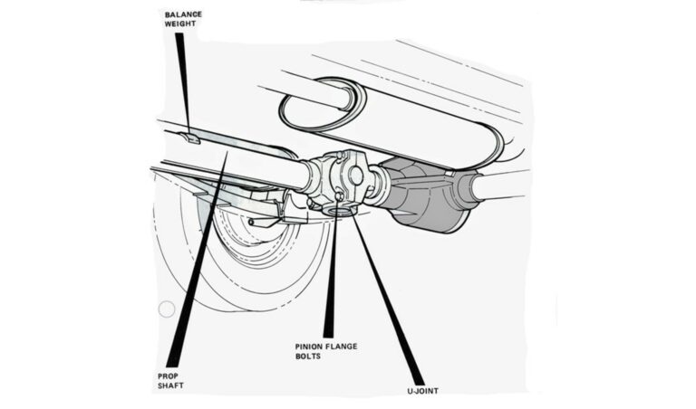
If you believe the driveshaft is out of balance, first make sure that the problem is not due to a defunct U-joint, an excessively worn slip yoke or transmission tail shaft housing, wheel imbalance, or excessive runout of the shaft itself (generally, this should not be more than about 0.040 in. as measured with a dial indicator).
Next, give the shaft a thorough visual inspection. Make sure it is clean–in high gear, it rotates at the same speed as the engine, so a lump of undercoating would be enough to give a car the shakes–then look for evidence of a thrown balance weight. Also, see if it is bent.
If you still have not found the trouble, disconnect the shaft from the rear, rotate it 180°, bolt it back up, and road test. If the vibration is still present, you can resort to the old hose clamp trick:
- Raise and support the car as safely and solidly as you can with the rear wheels off the ground.
- Start it up, put it in gear, and have a helper step on the gas and rev it up to 40 to 50 mph.
- Tape a piece of chalk or a crayon to a broomstick, hold it firmly with both hands and slide it under the car. Slowly move it so that it has the least possible contact with the shaft just ahead of the rear joint, then just behind the one at the front. The heavy side will be making a larger circle than the light one, so the mark should appear where the excess weight is.
- Shut the engine down and install two worm-gear hose clamps around the shaft with their heads 180° from the mark you just made.
- Rev it up to 65 to 70 mph and see if the vibration has disappeared. If it has, give it a road test to be sure. If it has not, rotate the clamp heads about 45° away from each other and try again. Getting better? Then keep moving the clamp heads apart until you get it right.
As you probably know, the basic function of a U-joint is to allow two shafts to operate at an angle to each other. But you may not realize that while the driving yoke rotates at a constant speed, the driven one speeds up and slows down twice during each revolution. At an angle of 4°, the variation in speed is a negligible 0.5 percent. At 10°, however, the change is 3 percent, and at 30° with the yoke going 1000 rpm, its partner goes from 866 to 1155 rpm each quarter of a revolution. You can imagine the surging vibration such an arrangement would set up.
Fortunately, this condition is eliminated using two joints with the driving yokes rotated 90° from each other. If the angle of each joint is about the same, the acceleration and deceleration of one is canceled out by the deceleration and acceleration of the other, and a smooth transmission of power is accomplished.
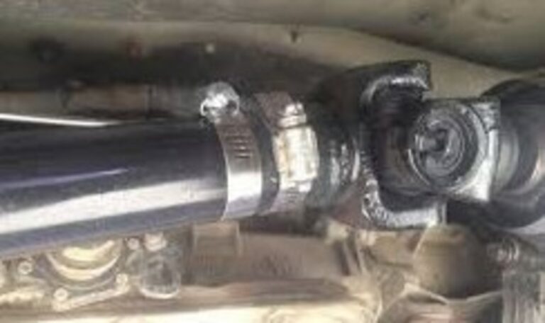
Hose clamps are an acceptable field fix for a missing balance weight. Move the heads apart to adjust the weight.
A good reminder with this project is that if you replace 1 u-join; you might as well replace the second while you have the drive shaft out as if one has gone bad the other is like on its way.
This is a simple overview of drive line vibration sources and repairs. There are loads of You Tube videos and web articles on u-joints that are classic car specific on replacing these parts.