This is one of those out of sight out of mind topics; until you experience a mysterious vibration while driving your classic car. Also, in most cases of restoration and in some cases in modifications no adjustments are required, but it is helpful to understand the meaning of the car pinion angle, and how to correctly adjust your classic car.
The car’s drivetrain pinion angle simply refers to the angle of the differentials pinion in relation to the driveshaft. But ask 10 guys about optimal pinion angle and a lively debate will ensue. To get a range of opinions, we spoke to several chassis builders about pinion angles. While their recommendations differ somewhat, they all agree on some basic principles. We will give you their take on the subject and show you the various ways to measure and correct this especially important aspect of chassis tuning.
Due to the dynamic nature of an automobile chassis, the various angles and symmetries are constantly changing, which adds to the complexity of obtaining driveline nirvana. Furthermore, we live in the real world where time takes its toll on our automobiles. Engines may not sit squarely in their motor mounts, motor mounts may not sit properly between the frame-rails, crossmembers may not sit straight, and who knows where the rear-end is positioned (ours is usually in a chair behind a desk). Despite all these factors affecting the positioning of our drivetrains, they seem to work well enough in most cases, at least on the street in basically stock applications. We owe this functionality to the universal joint, which, by design, corrects for slight misalignments between the driving components (crankshaft and transmission) and the driven components (driveshaft and differential) of the drivetrain. The truth is pinion angle can move significantly and well-tuned cars are setup to compensate.
What is with big deal with pinion angle?
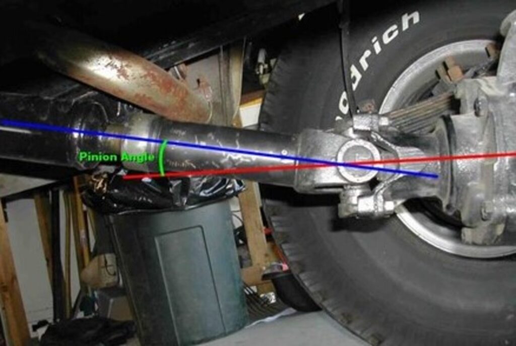
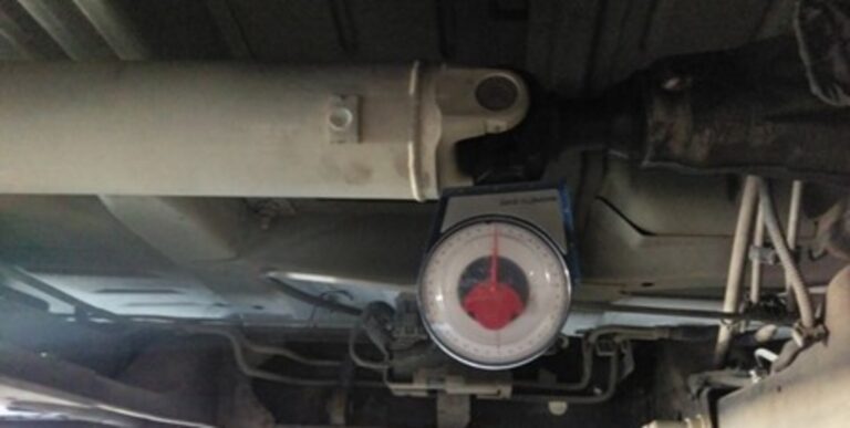
It is a noticeably big deal. To keep the driveshaft and U-joints operating in a (more or less) straight line, the pinion angle must be correct. Typically, the pinion angle is measured between the pinion gear flange and the driveshaft as well as the transmission slip yoke and the driveshaft. And the critical nature of pinion angle is such that it is important in everything from a low rider to a race car to a lifted 4×4.
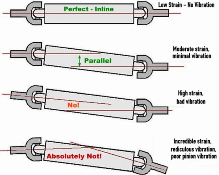
Using a high-performance car as an example, consider the rear suspension in the car when it is under power and it “wraps up.” Here, the pinion is driven upward (out of whack). The optimal angle for any driveshaft to run at is 1/2 degree, where many vibration and frictional problems are non-existent. To minimize power loss and vibration in an offset configuration, the pinion centerline and the transmission centerline need to be parallel. In general, the largest angle for racing applications should be 2 degrees and the centerlines should be parallel within a few 1/10 of a degree. If the chassis has some type of a parallel traction bar system, the angles should remain parallel throughout the suspension travel.
Keep in mind that with suspension movement the operating angle will increase but should not exceed a few degrees. If the parallelism of the centerlines changes, the U-joints travel at uneven operating velocities, causing vibration (this is the same problem induced by poorly phased end yokes). This vibration is hard to distinguish from an unbalanced driveshaft.
The pinion angle should be checked and adjusted any time there are changes in the chassis that influence the ride height or the length and location of the suspension link bars. The other thing you should keep in mind when it comes to the driveshaft is critical speed. Critical speed is the speed at which a spinning shaft will become unstable. This is one of the single largest factors in driveshaft selection. When the whirling frequency and the natural frequency coincide, any vibrations will be multiplied–so much that the shaft may self-destruct. Another way to think of this is that if a shaft naturally vibrates at 130 times a second, and one point on the shaft passes through 0 degrees 130 times a second (7,800 rpm) then the shaft has hit a critical speed.
There are several ways to raise the critical speed of a driveshaft. You can make it lighter, stiffer, or increase diameter without increasing weight. This is the reason carbon fiber makes a good driveshaft. It is stiff and light and can be made to any diameter or wall thickness. Aluminum has a higher critical speed compared to steel (same diameter and length shaft), but it is not quite as strong as steel. Steel, with its good strength characteristics, will have a lower critical speed. Because of this, it is important to check with a driveshaft manufacturer before you decide upon a specific driveshaft for a specific application.
Optimum Pinion Angle
Sometimes corrections need to be made at the front of the vehicle to ensure that the engine and trans are sitting in the proper location. The average classic car enthusiast should strive for between 1 and 3 degrees between the tail-shaft of the transmission and driveshaft, and 1 to 3 degrees between the driveshaft and pinion. Furthermore, the two angles should be nearly equal (between 1 and 3 degrees), but always opposite.
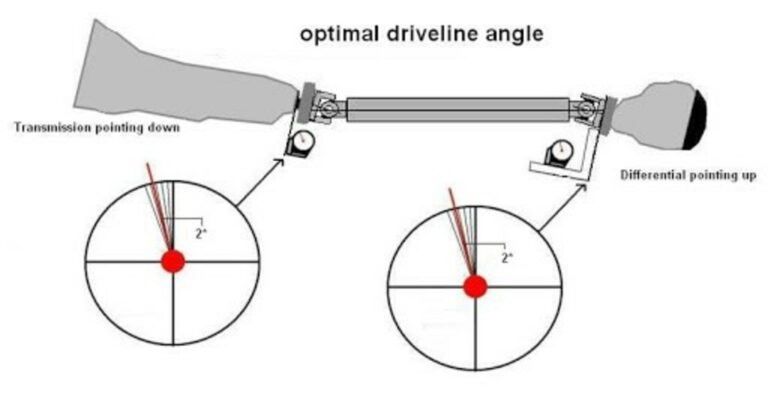
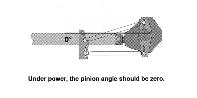
Setting the pinion angle is the final step in driveline alignment. The goal is to create a straight line from the back of the crankshaft through the transmission, driveshaft, and the pinion of the differential under load. Due to the tendency of the pinion to rise under load, some angle must be present at rest.
How well the rear suspension controls the position of the rear-end is the most critical issue that determines how much pinion angle will be needed. Some types of rear suspensions offer more control than others and require different angles. A ladder-bar suspension normally requires degree of pinion angle, a four-link requires 1-2 degrees, and a leaf-spring suspension requires up to 6 to 7 degrees. In all examples, were talking about negative pinion angle, i.e., the pinion is nose-down in relation to the driveshaft. A straight driveline delivers the most power to the rear wheels. A universal joint is designed to handle between 1 and 3 degrees of pinion angle. This is a safe operating range for the U-joint. If the U-joint is forced beyond its normal range, it can hyperextend and lead to catastrophic failure.
With a leaf spring equipped car, the differential movement is not nearly as controlled as that of a four-link suspension, so more angle may be needed to prevent the U-joint from hyperextending beyond zero degrees under load. Sometimes people increase the pinion angle to increase dragstrip bite, but this is not recommended approach for a street car. In general, the greater the pinion angle, the more horsepower the driveline will consume, but it is a compromise that must be made.
Setting Pinion Angle
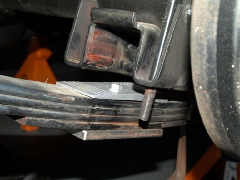
Probably the two most common rear-suspension configurations to come out of Detroit on muscle cars are the four-link and leaf-spring suspensions. On four-link equipped automobiles, adjustable upper control arms are required to change the pinion angle (although in some cases, mild adjustments can be made by shimming the transmission mount). This is made possible by adjustable upper control arms from several aftermarket sources. In the case of a leaf spring equipped classic car, pinion angle is changed with angled wedges (shims) that are placed between the leaf spring and the shock-absorber mount. These wedges effectively rotate the differential forward or backwards depending on which way the wedge is facing.
To ensure that the pinion is in the correct location under power, it is typically set nose down static. Some of the most common information (or perhaps misinformation) on setup was derived from the early years of Mopar racing. The early Chrysler cars had a very thick spring and were subject to wind up. To make allowances for this wind up, the pinion was dropped down a few degrees. This was done to keep the center lines running close to parallel when under power. If the car has OEM style rubber suspension bushings, a pinion angle of -3 to -4 degrees is likely more appropriate. This nose-down attitude was originally done to compensate for the compression of the rubber bushings.
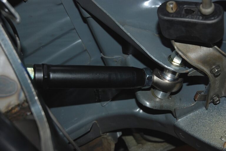
To set the pinion angle on a four-link car with adjustment capability (for example, a drag race four-link), you lengthen or shorten one or both upper four link bars to move down or up. On a triangulated four link (factory GM or Ford), the upper bars are also used to set the pinion angle (by adjusting both uppers the same direction and same amount). If the vehicle is equipped with leaf springs, then you can use wedge-shaped aluminum shims to move the pinion up or down. The wedges effectively rotate the pinion upward or downward depending on which way the wedge is facing. The shims are designed to sandwich between the rear-end housing perches and the leaf springs. You can also buy rear block kits engineered with a taper to move the pinion up or down.
Whether it is for a 16-second vintage car driver or an 8-second door-slamming classic car, the proper pinion angle is vital for delivering power safely and effectively to the rear wheels.
Correct me if I’m wrong. The engine and transmission always go down at ride height the pinion yoke goes down so under power it moves up to be level or at an opposite angle than the transmission. What about side to side angle? Maybe moving engine to left for more left side weight [oval track car] need to keep rear end in stock location. Thanks
You are correct that moving the engine to the left or right as lesser of an impact than up or down. Angles do matter though not to go beyond a certain point to binder the axel
Paul; you are correct the engine should tilt down and the rear end tilt up with both angles being at about 3% to allow for suspension travel without the driveshaft binding.
Thanks for the Quick reply I’m I correct about the engine /trans. angles? This what I’ve used on oval track cars. What works best for a high performance street car? I’m helping a friend trying to put together a car he bought. It’s together and have it at ride height. Has 4 link rear with adjustable upper arms and can modify or shim trans. mount. Also it has a short driveshaft. Thanks
Transmission Angle 5.1 Down & Pinion Angle 5.1 Up. Will This Work For A Street Car ? ? ? Thanks.
It would be best to get as close as you can to 3
Thanks